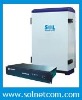

DTV Frequency Shift Repeater signal is relayed via radio frequency wave of frequency different from the TV transmitter
The DTV Frequency Shift Repeater (FSR) is designed to solve problems of weak mobile signal, which can expand more coverage than RF repeater and reduce investment for the areas where fiber optic cable is not available.
The repeater is working as a relay and frequency converter between the TV transmitter and receivers during the broadcasting of digital TV signal. It receives low-power TV signal from the TV transmitter via the Donor Antenna, then converts it to specified frequency, and retransmits it via the Coverage Antenna to the weak/blind coverage area. The FSR can avoid self-oscillation which will be easily caused by the RF repeater.
See the overview of Digital TV Repeater .
Application Diagram of DTV FSR
FeaturesAluminum-alloy casing with IP65 protection has high resistance to dust, water and corroding; Signal of up to 4 channels can be shifted and amplified simultaneously; Linear power amplifier with high gain and low noise is adopted; Filter with high selectivity and low insertion loss eliminates out-of-band interference; Best solution to eliminate self-oscillation problem caused by RF repeater; Omni-directional coverage antenna can be adopted for wider coverage range and easier choice of installation site; RS-232 ports provide links to a notebook for local supervision and to the built-in wireless modem to communicate with the NMS (Network Management System) that can remotely supervise repeater’s working status and download operational parameters to the repeater. ApplicationTo expand signal coverage or fill signal blind area where digital TV signal is weak or unavailable.
Outdoor: Airports, tourism regions, golf courses, tunnels, factories, mining districts, villages, highways… Indoor: Hotels, exhibition centers, basements, shopping malls, offices, parking lots, …The DTV FSR is mainly applicable to such case:
Remote suburb area or village where DTV spectrum deployment is clear and flexible.In comparison with RFR (RF repeater) and FOR (fiber optic repeater), the FSR has the following benefits and disadvantages:
| No more self-oscillation and easy to choose installation location; A full 360-degree coverage can be realized. | High signal noise may be introduced since the Donor Antenna picks up signal from the air; A certain frequency resource is required to be occupied. |
| DTV Frequency Shift Repeater | ||
| Working Frequency (customizable) | 167~223MHz / 470~862MHz | |
| Bandwidth of Each Channel | 8MHz | |
| Output Power (customizable) | 33~43 dBm (2~20 W) | |
| Gain | ≥ 90dB | |
| Gain Adjustment Range | 1~31dB @ step of 1dB | |
| Frequency Error | ≤ 0.05ppm | |
| ALC (Automatic Level Control) | @ maximum output power: input signal level increases by 10dB, increase of output level will be < 2dB or closed | |
| MER (Modulation Error Rate) | ≤ 0.8dB and variation < 1dB @ 10dB compression | |
| BER (Bit Error Rate) | Degradation ≤ 1*10-2 | |
| Voltage Standing Wave Ratio (VSWR) | ≤ 1.3 | |
| Noise Figure | ≤ 8dB | |
| In-Band Ripple | ≤ 3dB p-p | |
| Max. Input Level | ≥ -10dBm | |
| Spurious Emission | ≤ -36dBm | |
| In-Band Intermodulation Attenuation | ≤ -40dBc/30kHz | |
| Shoulder Level | Per Channel | ±4MHz offset from central frequency: ≤ -36dBc/30kHz |
| Per Band | Offset from edge of working band ≥ 8MHz: ≤ -40dBc or ≤ -13dBm/30kHz | |
| Offset from edge of working band ≥ 16MHz: ≤ -60dBc or ≤ -33dBm/30kHz | ||
| System Delay | ≤ 5.0μSec | |
| I/O Impedance | 50Ω | |
| RF Connector | N-Type (Female) | |
| Temperature Range | Operation: -25°C ~ +55°C / Storage: -30°C ~ +60°C | |
| Relative Humidity Range | ≤ 95% (non condensing) | |
| Power Supply (customizable) | DC +24V / AC 220V±15%, 50Hz / AC 110V±15%, 50Hz | |
| Backup Power Supply (optional) | 4 hours | |
| Casing Level | IP65 | |
| Dimensions | 630mm X 400mm X 230mm | |
| Weight | 35kg | |
| Remote Monitoring/Control via NMS | Supported | |
DTV Frequency Shift Repeater