
Detailed Product Description
Introduction
Meter case
The meter case complies to the insulating protective-class .
Terminal block
The terminal block is molded of heat-and flame-resistant bakelite. It is fixed in the extended meter base. The voltage test link can be located inside or outside of the meter case.
Driving element
The driving element consists of a voltage element and a current element, both of which are fixed on the aluminum alloy frame. It has a load curve compensation device and inductive load adjustment mechanism.
Rotor
The rotor shaft is turned of high strength aluminum alloy. Bras or plastic worm is also available. The worm and shaft can be detached.
Braking element
The magnet is made of AINiCo5 alloy and designed as U-shaped so that the effect of short-time over currents upon the magnet is negligible.
Frame
The frame is die-casted by high-qualiy SiAl alloy of stable property to avoid distortion. A low load adjustment mechanism which can be manually adjusted is mounted on the frame.
Upper bearing
The upper bearing consists of a guide pin and a brass sleeve, and is fixed on the meter frame with one screw.
Lower bearing
The meter uses holistic hard ferrite magnetic bearing unless there is special request from the customer.
Register
The register adopts heat-and abrasion-proof plastic gears and bearings. No lubrication of bearings is needed during the service life. The drum is made of polycarbonate, and is pyrographed and printed by UV resistant alumina to ensure non-depigmentation.
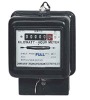
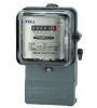
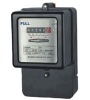
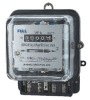
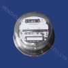
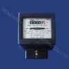
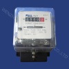
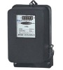
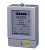
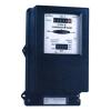
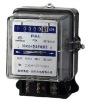
Single Phase Watt-Hour Meter
Typical connection diagram of Single Phase Watt-Hour Meter
Outline & Installation Size of Single Phase Watt-Hour Meter
Technical Data
1 | Meter type | DD450 |
2 | Applicable Standards | IEC60521. BS5685 |
3 | Accuracy | Class 2 (according to IEC60521) |
4 | Average service life (MTTF) | 20 years |
5 | Basic current (lb) A | 5 10 15 |
6 | Maximum current (lmax) A | 20 30 40 60 80 100 |
7 | Reference voltage Un | 110V,120V,220V,230V,240V |
8 | Reference frequency fn | 50Hz, 60Hz |
9 | Power losses in voltage circuit at 50Hz Un | For over load capacity of 800%lb:1.3W/6VA others:1.0W/5VA |
10 | Power losses in current circuit at 50Hz Un Ib | <0.5VA |
11 | Non-running with no-load | 0.8~1.1Un |
12 | Starting current | 0.5%lb |
13 | Mean temperature coefficent: Form0.1lb to lmax at unity PF Form 0.2lb to lmax at unity 0.5lagging | <0.08%/ <0.12%/ |
14 | Insulation level: Withstanding A.C. voltage for 50Hz, 1min Withstanding impulse voltage 1.2/50us | >4kV >8kV |
15 | Rated load torque at unity PF, lb | Over load capacity 800%lb:350uNm Over load capacity 400~600%lb:400uNm |
16 | Weight of rotor | 23.5g |
17 | Weight of meter | 1.6kg |
18 | Main case | Bakelite base/PC cover/bakelite terminal cover |
19 | Register | Cyclometer single, unidirectional, Jumping |
20 | Option | Reverse running stopper |