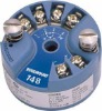
Rose mount Temperature Transmitter 248

Detailed Product Description
Industry standard DIN Form B headmount
transmitter size enables mounting in any
connection head
New compact DIN railmount style
Reliable EMC performance meets NAMUR
NE21 recommendation
Communicates using open 420 mA/HART®
Protocol
A 248C PC-based HART configuration
interface is available;
FUNCTIONAL SPECIFICATIONS
Inputs
User-selectable; sensor terminals rates to 42.4 V dc. See
Transmitter Accuracy and Ambient Temperature Effects on
page 4 for sensor options.
Output
2-wire 420 mA, linear with temperature or input; digital output
signal superimposed on 420 mA signal, available for a HART
communicator or control system interface.
Isolation
Input/output isolation tested to 500 V ac rms (707 V dc) at 50/60
Hz.
Power Supply
An external power supply is required for HART devices. The
transmitter operates on 12.0 to 42.4 VDC transmitter terminal
voltage with load resistance between 250 and 1100 ohms. A
minimum of 17.75 VDC power supply is required with a load of 250
ohms. Transmitter power terminals are rated to 42.4 V DC.
Humidity Limits
099% relative humidity, non-condensing
NAMUR Recommendations
The 248 meets the following NAMUR recommendations:
NE 21 Electromagnetic compatibility (EMC) for Process and
Laboratory Apparatus
NE 43 Standard of the signal level breakdown information of
digital transmitters
NE 89 Standard of temperature transmitters with digital
signal processing
Transient Protection
The optional Rosemount 470 Transient Protector prevents
damage from transients induced by lightning, welding, heavy
electrical equipment, or switch gears. Refer to the 470 Product
Data Sheet (document number 00813-0100-4191) for
more information.
Temperature Limits
Operating Limit
40 to 85 °C (40 to 185 °F)
Storage Limit
50 to 120 °C (58 to 248 °F)
Turn-on Time
Performance within specifications in less than 5.0 seconds after
power is applied to transmitter, when damping value is set to zero
seconds.
Update Rate
Less than 0.5 seconds
Damping
32 seconds maximum. 5 seconds default
Custom Alarm and Saturation Levels
Custom factory configuration of alarm and saturation levels is
available with option code C1 for valid values. These values can
also be configured in the field using a HART Communicator.
Recommended Minimum Measuring Span
10 K
Software Detected Failure Mode
The values at which the transmitter drives its output in failure
mode depends on whether it is configured to standard, custom, or
NAMUR-compliant (NAMUR recommendation NE 43) operation.
The values for standard and NAMUR-compliant operation are as
follows:
Certain hardware failures, such as microprocessor failures, will
always drive the output to greater than 23 mA.
PHYSICAL SPECIFICATIONS
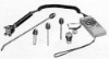
HART Communicator Connections
Communication Terminal: Clips permanently fixed to the terminals
Materials of Construction
Electronics Housing
Noryl® glass reinforced
Universal (option code U and H) and Rosemount® Connection
(option code A and G) Heads
Housing: Low-copper aluminum (option codes U and A)
Stainless Steel (option codes G and H)
Paint: Polyurethane
Cover O-Ring: BunaN
BUZ Head (option code B)
Housing: Aluminum
Paint: Aluminum lacquer
O-Ring Seal: Rubber
Mounting
The 248R attaches directly to a wall or a DIN rail. The 248H
installs in a connection head or universal head mounted directly on
a sensor assembly or apart from a sensor assembly using a
universal head. The 248H can also mount to a DIN rail using an
optional mounting clip (see Table 18).
Weight
Enclosure Ratings
The Universal (option code U) and Rosemount Connection (option
code A) Heads are NEMA 4X, IP66, and IP68. The Universal
Head with 1/2 NPT threads is CSA Enclosure Type 4X. The BUZ
head (option code B) is NEMA 4 and IP65.
PERFORMANCE SPECIFICATIONS
EMC (ElectroMagnetic Compatibility)
NAMUR NE21 Standard
The 248 meets the requirements for NAMUR NE21 Rating
CE Mark
The 248 meets all requirements listed under IEC 61326:
Amendment 1, 2006.
Power Supply Effect
Less than ±0.005% of span per volt
Vibration Effect
The 248 is tested to the following specifications with no effect
on performance:
Stability
For RTD and thermocouple inputs the transmitter will have a
stability of ±0.1% of reading or 0.1 °C (whichever is greater) for
twelve months
Self Calibration
The analog-to-digital measurement circuitry automatically
self-calibrates for each temperature update by comparing the
dynamic measurement to extremely stable and accurate internal
reference elements.
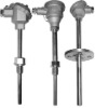
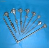
THERMOCOUPLES IEC 584
Applicable to sensors offered in Table 13 on page 12
and Table 14 on page 14
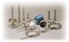
Construction
Rosemount DIN plate and 1/2-in. adapter style thermocouples are
manufactured from selected materials to meet IEC 584 Tolerance
Class 1. The junction of these wires is laser-welded to form a pure
joint, maintaining circuit integrity and ensuring highest accuracy.
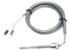
Lead Wires
Internal 18 SWG (16 AWG) solid wire (max), 19 SWG (18 AWG)
solid wire (min.). External extension leads, type J and K 0.8 mm
minimum stranded wire, PTFE insulation. Color coded per IEC 584
Insulation Resistance
1000 Megaohms minimum insulation resistance when measured
at 500 V dc at room temperature.
THERMOCOUPLES ASTM E 230
Applicable to sensors offered in Table 15 on page 16
Construction
Rosemount 1/2-in. adapter style thermocouples are manufactured
using ISA Type J or K wire with special limits of error accuracy.
The junction of these wires is fusion-welded to form a pure joint, to
maintain the integrity of the circuit and to ensure the highest
accuracy.
Lead Wires
Thermocouple, internal 16 AWG solid wire (max), 18 AWG solid
wire (min.). External lead wire 20 AWG wire, PTFE insulation.
Color coded per ASTM E-230
Insulation Resistance
100 Megaohms minimum insulation resistance when measured at
100 V dc at room temperature.
RTDs
Sensor Type
100 ohm RTD at 0 °C, α = 0.00385 ohms/ohm/°C.
Accuracy
Meets IEC 751 Class B tolerances
Temperature Range
50 to 450 °C (58 to 842 °F)
Self Heating
0.15 °K/mW when measured per method defined in
DIN EN 60751:1996 or 16 mW minimum power dissipation
required to cause a 1 °C (1.8 °F) temperature measurement error
in water flowing at 0.91 m/s (3 ft/s)
Thermal Response Time
9 seconds maximum required to reach 50% sensor response
when tested in flowing water according to IEC 751 or 12 seconds
maximum required to reach 63.2% sensor response in water
flowing at 0.91 m/s (3 ft/s).
Immersion Error
60 mm minimum usable depth of immersion when tested
according to IEC 751.
Insulation Resistance
500 Megaohms minimum insulation resistance when measured at
500 V dc at room temperature.
Sheath Material
321 SST with mineral-insulated cable construction.
Lead Wires
FIGURE 1. Transmitter Housing Temperature
Rise vs. Uninsulated Extension Length
for a Test Installation