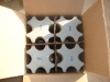

Cap and Pin Type Insulator: ANSI Standard Insulator: 55-1,55-2,55-3,55-4,55-5,55-6,55-7
ANSI | 55-1 | 55-2 | ||||
Insulator Type | Plain | Radio Freed | Plain | Radio Freed | ||
Neck Designation in accordance with ANSI C29.5 | C | C | ||||
Voltage Rating (U.S.Practice) /KV | 7.2 | 7.2 | ||||
Leakage Distance/in (mm) | 4(102) | 5(127) | ||||
Dry Arcing Distance/in (mm) | 2-1/4(57) | 3-3/8(86) | ||||
Minimum Pin Height/Average/lb (kN) | 3,000(13.3) | 2,500(11.1) | ||||
Average Flashover Voltage | Low-frequency | Dry/kV | 35 | 35 | 50 | 45 |
Wet/kV | 20 | 20 | 25 | 25 | ||
Critical-impulse | Positive/kV | 50 | 50 | 75 | 70 | |
Negative/kV | 70 | 70 | 95 | 85 | ||
Low Frequency Puncture Voltage/Average/kV | 50 | 70 | ||||
Radio-Influence Voltage Date | Test Voltage to Ground/kV | 5 | 5 | 5 | 5 | |
Maximum RIV at 1,000kHz/μV | 2,500 | 50 | 2,500 | 50 | ||
Net Weight/lb | 1.2 | 1.4 | ||||
1.Surfaces coated with semi-conductive glaze considered as effective leakage surfaces and the distance over them is included in the leakage distance.
2.Top-and wire groove shall seat a mandrel with a diameter of 15/16 inch.
ANSI | 55-3 | 55-4 | 55-5 | |||||
Insulator Type | Plain | Radio Freed | Plain | Radio Freed | Plain | Radio Freed | ||
Neck Designation in accordance with ANSI C29.5 | C | F | F | |||||
Voltage Rating (U.S.Practice)/KV | 7(178) | 9(229) | 12(305) | |||||
Leakage Distance/in (mm) | 4-1/2(114) | 5(127) | 6-1/4(159) | |||||
Dry Arcing Distance/in (mm) | 5(127) | 5(127) | 6(152) | |||||
Cantilever Strength/Average/lb (kN) | 2,500(11) | 3,000(13) | 3,000(13) | |||||
Average Flashover Voltage | Low-frequency | Dry/kV | 65 | 55 | 70 | 65 | 85 | 80 |
Wet/kV | 35 | 30 | 40 | 35 | 45 | 45 | ||
Critical-impulse | Positive/kV | 100 | 90 | 110 | 105 | 140 | 130 | |
Negative/kV | 130 | 110 | 140 | 130 | 170 | 150 | ||
Low Frequency Puncture Voltage/Average/kV | 90 | 95 | 115 | |||||
Radio-influence Voltage Date | Test Voltage to Ground/kV | 10 | 10 | 10 | 10 | 15 | 15 | |
Maximum RIV at 1,000kHz/μV | 5,500 | 50 | 5,500 | 50 | 8,000 | 100 | ||
Net Weight/lb | 2.4 | 3.7 | 6.4 | |||||
1.The side-wire groove shall seat a mandrel with a diameter of 1-1/16 inches. The top-wire groove shall seat a mandrel with a diameter of 1-3/4 inches.
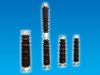
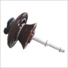
LOW AND MEDIUM VOLTAGE PIN TYPE INSULATOR(ANSI STANDARD)