
PLC Frequency cabinet 1. Proof of intrinsic safety 2. Test certificates 3. PLC - DCS interface configuration
PLC Frequency cabinet
Typically the control system comprises two local operator control panels at the filterdryer, a control cabinet and a switch gear cabinet (MCC) located in a safe area. A single operator panel only is normally used for vacuum dryers.
The primary operator control panel includes a terminal with colour display for the entering of machine parameters and for the display of process variables. The secondary operator control panel is intended for the operation of the solids discharge valve and agitator functions as well as for the opening and closing of the filter bottom. The operator controls of the local control panels are mounted in IP 65 rated stainless steel enclosures, all controls are rated intrinsically safe (EEx). The local operator panels, the transmitters for product temperature, internal vessel pressure, vessel level etc. required for the operation of the equipment, all safety and process related proximity switches and the required control valves are connected with the control cabinet.
The control cabinet with the PLC is designed for installation in a non-hazardous area. The control circuits in the control cabinet are split into an intrinsically safe area connected to the non hazardous area with EEx i barriers.
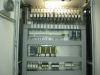
Installed in the control cabinet are the terminals for the intrinsically safe inputs and outputs (Picture left,upper right, blue), the inputs and outputs for the non hazardous area (Picture left, upper left), the EEx ibarriers (Picture left, lower right, green) and the PLC (Picture left, bottom, black).The switch gear cabinet contains all switchgear such as interrupters, contactors, relays, etc., as requiredto operate the electrical equipment supplied with the equipment such as motors and vessel lamps.Frequency converters if included in the scope of deliveries will also be installed in the motor controlcabinet.All electrical components are installed in IP 54 rated Rittal cabinets.
The control system is based on a PLC with all components as required for the operation of the equipment (COMBER scope of deliveries) including the software and all relevant interlocks for the safe operation of the equipment.The Siemens Simatic S7-300 series of PLC’s is typically used in Europe whereas in the Americas the Allen Bradley SLC 500 series is typically used. The PLC’s are equipped with the required number of digital and analog input and output modules.
Integrated RS 485-, Profibus- and Ethernet-Interfaces permit data co mmunication with other devices. This permits interfacing the PLC with a remote distributed control system (DCS) to permit remote control and monitoring of the equipment or data logging as required.If no distributed control system (DCS) is available or planned on the installation site we recommend the extension of the control unit software to provide for automated functions. These functions permit the automatic operation of the equipment, and also permit memorizing a number of operating programs.Parameters and functions for the automatic operation are entered or selected on the operator control panel.Alternatives to this conventional type of control system are available and include e.g. control systems using field bus devices.
A Functional Design Specification (FDS) comprising the description of the system architecture and the software specification for all functions as required is the basic document used for the design of the PLC control system hardware and software.Based on this Draw all other documents are developed such as terminal and circuit diagrams, cable lists, configuration diagrams, connection diagrams, part lists etc. as well as the software.
The control system, electrical, instrumentation and software documentation supplied with the equipment essentially comprises the following:• Component list and data for electrical components• Part lists with all electric and electronic components• Connection diagrams• Terminal diagrams• Configuration diagrams for control cabinet, switch gear cabinet, operator control panels andjunction boxes• Circuit diagrams• Cable lists• Functional Design Specification (FDS) with system architecture and software specifications• List of PLC inputs and outputs• PLC - DCS interface configuration• Proof of intrinsic safety• Test certificates• ATEX conformity declarations• Installation and operating manuals for instrumentation and electrical components• FAT protocol for control system• List of spare parts• Operation and maintenance manual
Control system PLC Frequency cabinet