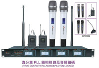

1.MR-4000U UHF PROFESSIONAL WIRELESS MICROPHONE 2.TRUE DIVERSITY/PLL/NOISE&PILOTON LOCKED 3.UHF
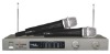
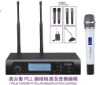
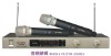
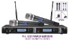
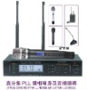
MR-4000U UHF PROFESSIONAL WIRELESS MICROPHONE
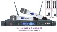
SPECIFICATION:
Frequency Response: UHF 672-6960.95MHz(1000 Tunable Frequencies)
Frequency Stability of PLL System: <0.005%
Audio Frequency Response: 30HZ ~18KHZ± 3dB
Modulation Mode: FM ( F3E ) ± 25 kHz (nomal ) ,± 75KHZ(max)
Power Adaptor: AC220V 50Hz or AC110V 50Hz(optional)
Squelch Control: Tone Squelch,Dual Mute Control
Audio lnput: Wireless Receiver
Wwight: Approx 2.06
Dimensions: 432*191*51mm
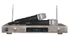
Includes: Receiver, Handheld Mic
FEATURES:
True diversity reception,UHF 672-6960.95MHz , avoiding different interences
Infrared ray , automatic frequency scan feature searches for available frequencies
LCD display provides a great deal of additional infomation at a glance
Adopting advanced PLL Synthesis , 1000 tunable frequencies
Lower power design helps microphone work 8-15 hours continuously (AA battery)
High gain antenna enhances working distance to more than 150m
Standard installing dimension
Specially suit for professional perfomance
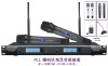
Receiver
1.Unsurpassed state-of-the-art PLL UHF performance with 120dB dynamic range and operation up to 500 feet line-of sight.
2.Two complete and independent wireless receivers with 1000 user-selectable UHF frequencies for simultaneous operation of two transmitters.
3.True Diversity circuitry with two complete front ends per receiver for maximizing range and most effective elimination of signal dropouts.
4.AUTO-SCAN for easily locating clear channels and ASC(AUTO-Sync Channel) IR download feature which sends selected Group/Channel information to transmitter via IR sender for easy frequency synchronization.
5.Sophisticated IF filtering for simultaneous operation of multiple systems in the same location.
6.Front panel touch control buttons and user-friendly LCD configuration menus.
7.Front panel backlit LCD display indicates selected Group,Channel,RF signal strength meter,A/B Diversity antenna status,Audio Output Volume Level,Separate audio/peak LED bar graph display providing instantaneous audio level status easily seen from a distance.
8.Back panel Balanced XLR Mic level and Unbalanced1/4'' SUM Line level audio output jacks,squelch control,RF BNC connectors for dual removable 1/2 wave antennas for each receiver,and DC power input jack supply.
9.Externally powered(adapter included)
10.Tugged all-metal housingrack mountable.
11.Works with any two combinations of available instrument,handheld and lavaier UHF transmitters.
Receiver : Front View
1.POWER BUTTON : Press for one second to turn both receivers ON-OFF
2.DIVERSITY A/B INDICATOU : Indicates receiver A or B is active when transmitter is on.
3.AF PEAK LED : Shows flickering GREEN LED is normal or solid GREEN LED is for maximum audio allowable.
4.IR : Infrared LED transmitter window for linking the RX to the TX for frequency download.
5.AUTO-SCAN/ASC (IR SYNC) BUTTON : Long press (hold~2 seconds) for AUTO-SCAN to locate a clear channel to use. Short press(~1 second) to make the IR link download the receiver's selected frequency to the TX. To download,position the HT-1KU/UBT-100 transmitters' IR Window about 3-12" away from the RX IR Window. Press the ASC Button once and wait one second for the RX to respond.If the download is successful,the RX will show one of the Diversity Antenna Icons and full RF LCD Bars on the LCD Display.
6.SET BUTTON : To scroll through the LCD menu and set the selected program/function.
7.UP BUTTON : To change the receiver LINE output VOL level, GRP/CH down by one step at a time.
DOWN BUTTON : To change the receiver LINE output VOL level,GRP/CH down by one step at a time.
8.LCD DISPLAYS : For indication of A-B Diversity, GRP (00-09)/CH(00-99),RF signal strength indicator 1-6 bars,and Volume Levels(0-63)
9.FREQUENCY GROUP : Indicates selected GROUP from 00-09
10.FREQUENCY CHANNEL : Indicates selected CHANNEL from 00-99
11.SUM VOLUME LEVEL : Indicates selected LINE output level from 00-63,(63 is loudest output)
12.RF SIGNAL METER : Indicates received signal strength level from 1-6 bars,(full 6 bars shows strongest incoming RF signal)
Receiver : Back View
13.DC INPUT JACK : For using supplied external AC/DC adapter to power the receivers.
13a.ANTENNA EXTENSION CABLES : Attach coax cables with BNC connectors from back antenna jacks to rack ear holes for front antenna mounting configuration.
14.RF CONNECTORS : Antenna jack A for RF True Diversity reception.
15.BALANCED MIC OUT : Audio output connection for each receiver-fixed Mic level.
16.MUTE (SQUELCH) CONTROL : Controls the mute level for each receiver-turn CW for maximum range;turn CCW for minimum range,if needed ,to minimize noises from outside RF interference upon muting
17.UNBALANCED AUDIO OUT SUM : Volume Level audio output for four receivers-adjustable LINE level.
18. DC INPUT JACK : For using external DC adapter to power the receivers.
19.RF CONNECTORS : Antenna jack B for RF True Diversity reception.
20.DC POWER SUPPLY UNIT : DC Adaptor connects to DC Input Jack.
21.ANTENNAS : 1/2 wave antennas connect to A/B Antenna Jack.
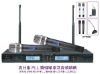
Handheld Transmitter
22.BATTERY COVER : Unscrew CW and full down to insert two AA alkaline batteries.
23.MIC BALL : Windscreen/dust cover.
24.LCD DISPLAY : For indication of GRP(00-09)/CH(00-99),AUDIO INPUT LEVEL (0dB TO -30dB),and BATTERY status (5 bars and "BATT" See 30/31/32/33 in HT-1KU transmitter diagram above for detail LCD display inficators.
25.UP BUTTON : To change the GRP/CH or VOL level up by one step at a time or to light up the display.
DOWN BUTTON : To change the GRP/CH or VOL Level down by one step at a time or to light up the display.
26.SET : To scroll through the LCD menu and set the selected program/function.
27.RF POWER SWITCH : Select the TX power level high or low output.
28.POWER ON/OFF SWITCH : Slide power switch up-down to turn ON-OFF.
29.INTERNAL ANTENNA : Built-in antenna.
30.FREQUENCY GROUP : Indicates selected GROUP from 00-09 or to light up the display.
31.FREQUENCY CHANNEL : Indicated selected CHANNEL from 00-99 or to light up the display.
32.INPUT VOLUME LEVEL : Indicates input audio level ranging from 00dB to - 30dB
33.BATTERY METER : Indicates battery status (5 bars=100%, 1 bar=20%).Change batteries when flashing "BATT"
34.IR RECEPTOR SENCOR/WINDOW : Infrared LED sensor for IR frequency download from RX.
35.BATTERY COMPARTMENT.
36.TWO AA ALKALINE BATTERIES.
Bodypack Transmitter
37.ANTENNA : Removable antenna-should be attached during poeration.
38.OFF/STDBY/ON SWITCH : Slide power switch to ON or OFF.Set to STDBY to turn power on with audio muted.
39.INPUT JACK : Locking 3.5mm mini-jack for connecting audio input cord from lapel mic. Headmic or instrument cable.
40.BELT CLIP : On back of unit
41.LCD DISPLAY : For indication of GRP(00-09)/CH(00-99),AUDIO INPUT LEVEL (0dB to 30dB),and BATTERY status (5 bars to 1 bar and "BATT" See 27/28/29/30 in HT-1KU transmitter diagram above for detail on LCD display indicators.
42.IR RECEPTOR SENSOR : Infrared LED sensor for linking the transmitter to the receiver during IR frequency download.
43.LATCHING BATTERY COMPARTMENT DOOR : Slide open to insert batteries .
44.BATTERY COMPARTMENT : Holds two AA alkaline or NIMAH batteries.
45.INSTRNMENT CORD : GT cable-connects Instrument's audio output to TX input jack
46.HEADMIC : Headworn microphone-connects to transmitter input jack.
47.LAVALIER MIC. : Lavalier(lapel) microphone-connects to transmitter input jack.
MR-4000U UHF PROFESSIONAL WIRELESS MICROPHONE