
Detailed Product Description
I. Brief Introduction of the Product
A. Function and Usage
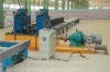
Horizontal flange correcting machine type SKHJ-C is used for correcting the flange of H-beam. The flanges of H-beam will be deformed after being welded, so it can only be used after correcting. The equipment is mainly used for correcting the flanges of H-beam after welding.
B. Specifications and Devices
1. Flange width: 200~800mm
2. Flange thickness: 8~40mm Q345 (Correcting 40mm of thick plate means the width of flange is > 700mm
8-60mm Q235 (Correcting 40mm of thick plate means the width of flange is > 600mm
3. Web height: 250~1500mm
4. Correcting speed: 4500mm/min
5. The main driving motor power: 5.5kw×2
6. The highest pressure of hydraulic system: 25Mpa
7. Hydraulic driving motor: 7.5kw
8. Front rollers of the correcting machine 8000mm (one set of driving clutching rollers, one set of auxiliary rollers)
9. Back rollers of the correcting machine 8000mm (one set of driving clutching rollers, one set of auxiliary rollers)
II. Overall Dimension of the Machine
Length: 6000mm Width: 2220mm Height: 3000mm
III. Structure and Composition
It is adopted with horizontal correcting structure. The left flange correcting machine is fixed, and the right flange correcting machine can correct as the changing of the height of web in traveling.
It uses power roller mechanism, and it can vertically and horizontally move in order to meet the central height changing of H-beam.
Right flange correcting machine can horizontally move on the rollers, and the right main machine can complete the correcting of the flanges in traveling when the height of web is changing.
The machine also uses hydraulic system correcting power and the balance pointer wheel deceleration machine, which is fast in speed and small in bulk. So the smooth driving in low speed is realized in this way
.
IV. Technical Data and Parameters
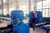
A. Control Cabinet
The control cabinet is a control device matched with the flange correcting machine on the welding production line of H-beam. A site operation box is provided, so it can realize the control at two places. There are two 5.5kw of main motors and a 7.5kw hydraulic motor on the flange correcting machine. The equipment is mainly used for correcting the steel plate. The main motor has forward, backward and touch control functions. The main electrical components are imported from or manufactured in joint ventures.
Control
1. Main Circuit Control
QF1 is the switch for main power source. QF2 and QF3 are broken circuit switches of left and right main driving motors, QF5 and QF7 are broken circuit switches of conveying motors. QR1 and QR2 are hot relays of main motors, which are used to protect the motors. KM1 and KM2 are the forward and backward contactors of main motor; KR2 is hot relay of left and right motor. The automatic air switch is available for protecting of short circuit for the motor, and the hot relay is for protection of overheating of the motor.
2. Protection Circuit
QF8 is an automatic air circuit breaker, and it has circuit protection function in control circuit. There is an emergency button on the control box and site operation box for emergency stop. FR1 is overheating protected relay for main motor, FR2 and FR3 are overheating protected relays of left and right motors. XW1 and XW3 are hoisting spacing switches for left and right motors, and XW2 and XW4 are descending spacing switches for left and right motors. There are three pilot lights on the panel. BL1 is the indicator for power source, HL2 is the forward indicator for main motor and HL3 is the backward indicator for main motor. S3 is forward or stop optional switch of main motor. S2 is clockwise rotation and stop optional switch of main motor, which is on the site operation box. S4 is reverse rotation and stop optional switch of main motor, which is on the site operation box. ST1 and ST2 are forward and backward touch control buttons of main motors. ST5 and ST6 are forward and backward touch control buttons of main motors, which are on the site operation box.
3. Operation of Control Circuit
Close the main switches Q1, Q2 and Q3 and control switch QF8. The main pilot light HL1 shines. And it can touch adjust the left and right motors at this time, then put the optional switch S1 on the forward position of main device. Contactors KM1 and KM4 shall contact to close. For several seconds later, KM4 is open and KM3 is close. After the starting of main motor, pilot light HL2 shines, and it shows the motor operates normally.
V. Working Condition for the Equipment
Temperature: -5~ 45
Power supply: 380V, 50HZ
The persons to be trained shall graduate from senior middle school.