Detailed Product Description
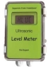
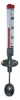
level meter
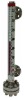
RF Admittance Level Meter
RF admittance level meter, capacitance level meter
RF admittance level meter is a kindly improved capacitive measurement technique.
Measuring principle
RF admittance measurement technique is a capacitive measurement technique developed. That is, the concept of radio frequency output of a high frequency sine wave signal, used to measure the test sensor container and metal electrode between the container wall admittance. RF admittance measurement technique is superior to the traditional capacitive measuring technology, not only because it can be measured capacitance measurement of resistance at the same time.
Adhesion to a conductive liquid sensing electrode in the hanging material layer, the capacitance measurement will increase, this is not the true level of capacitance. Linked to only a very thin layer of material, its surface contains far less than the transverse cross-containing material surface, so the resistance of materials is very small, and linked to the resistance of materials is great. From the electrical point of view, the sensor electrode is expected to be linked to cover a considerable part of numerous infinitesimal by the capacitance and resistance of the composition of the transmission line, according to electrical theory, if the material hanging long enough, the material linked to the same capacitive reactance and resistance . Application of phase-sensitive detection circuit can be measured capacitance value and resistance value.
Since the measured total capacitance C = C Level + C linked material, and C linked to expected value of the capacitive reactance in the equivalent to R. C can be the current value of the objects. This RF admittance sensing technology can be an effective solution to the electrode materials linked to the issue of the roots, thereby enhancing measurement accuracy.
Performance Indicator.
Power DC24V OR AC220V,Power <1.6W
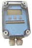
Display LCD
Transmission output 4-20m A OR 1-5V
Alarm mode There are two independent alarm relays, each with a normally open contact, the police can be a lower limit or upper limit of alarm, the margin can be set back.
Measur range 0-3000PF
Resolution ≤0.2PF
Measurement accuracy ±1%
Calibration Any two-site calibration
Communications 485 OR 232
Instrument set
1st parameter (When the password for the 132 or 1879, you can set)...
Set parameter | Name | Set Range | caption | Ex-factory value |
| SL0 | Decimal point position | SL0=0 | No show decimal point |
|
SL0=1 | Show a decimal point | |||
SL0=2 | Show two decimal places | |||
SL0=3 | Show three decimal | |||
SL1 | Alarm 1 way | SL1=0 | Not alarm |
|
SL1=1 | Lower limit alarm | |||
SL1=2 | Limit alarm | |||
SL2 | Alarm 2 way | SL2=0 | Not alarm | |
SL2=1 | Lower limit alarm | |||
SL2=2 | Limit alarm | |||
SL3 | Filter strength | SL3=0 | Weak filtering effect |
|
SL3=1 | Filtering role for the middle | |||
SL3=2 | Filtering effect for high | |||
| ALM1 | Set the value of the 1st alarm |
| ||
| AH1 | Set the margin back to the 1st alarm |
| ||
| ALM2 | The 2nd alarm set |
| ||
| AH2 | Set the margin back to the 2nd alarm |
| ||
| SLL | Limits set under the Meter | When the instrument in the normal operation of state, show that the lower limit level, transmission 4mA output current |
| |
| SLH | Set the upper limit of meter | When the instrument in the normal operation of state, show the upper limit level, transmission 20mA output current |
| |
| L0 | Field Calibration of the location of low level | After the calibration points and the corresponding level in the capacitor memory in E2ROM (Note 1) |
| |
| H1 | Field Calibration of high level positions | After the calibration points and the corresponding level in the capacitor memory in E2ROM |
| |
| BOT | Bps select | There are five. Divided into 300,600,1200,2400,4800,9600 |
| |
| dE | No. instrument set | Users of the device number of the meter set (0-255) |
| |
| Pb0 | Shows the value of zero migration | 0 | ||
| KK0 | Shows the value of magnification | 1.000 | ||
| Pb1 | Migration of zero transmission output | 0 | ||
| KK1 | Magnification transmission output | 1.000 | ||
2nd parameter (Only when the password set to 1897 in order to set up).
| OU04 | Calibration of the transmission output | Calibration of the transmission output is 4mA, the corresponding D / A value |
|
| OUT20 | Calibration of the transmission output | Calibration of the transmission output is 20mA, the corresponding D / A value.... |
|
.....