China patent product Use for simulating working state of circuit system,central control room, power station, switchboard
Application
MGZ2000 Series Simulating Working State Indicator can simulate connection of circuit system, working place and state of switch and circuit breakers etc, power supply situation of signal circuit, and can extensively used in the central control room simulation board of power factory and power station, all simulation board or switchboard or electric distribution and transformation.
Type and specification
The type, mark, name and diagram are following.
Rate working voltage (Un) has four types: 220VDC, 110VDC, 48VDC and 24VDC.
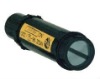
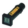
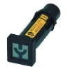
Structures features and outline dimension
MGZ2000 Series Simulating Working State Indicator is composing with junction, DC-DC (or AC-DC) change, signal acquisition, single chip micyoco, indicator board and housing. It have work credible, display accurate, good outline and convenient installing etc.
Technical parameters
Rate working voltage Un: 220,110,48,24VDC
Outline dimensions : 36mm×36mm×125mm
Diameter of install hole : φ25mm
Display time of respond: t1s
Power loss :ρ≤1.6VA
Insulation resistance : 100MΩ
Withstand voltage : 2.5KVDC
Limit with temperature rise for housing: ≤50
Condition of use and storage
1. Power supply: direct current 220V, 110V, 48V, 24V±10%
Ripple voltage coefficient S≤0.67
2. Environmental temperature: Around temperature humidity 24h average not more than
+35, the highest +40, and the lowest -5.
3. Humidity: the day average relative humidity 95% or down; month average relative humidity
90% or down.
4. Altitude above sea level: the altitude of installations place commonly not more than
2000m.
5. Seismic degree8, the place of no fire, blast risk, high chemistry corrosion and shock.
6. The strength of outline magnetic field 0.4KA/m
Connection Mode (Take example by Circuit Breakers)
1. The connections that its direct current for Circuit Breaker assistant loop.
2. The connections that its alternating current for Circuit Breaker assistant loop.
Installation Mode
MGZ2000 indicator installation
1) Take down back cover of indicator
2) Take down nut, outer sleeve and gaskets
3) Encasedφ25 install hole of switchboard, installed gaskets, outer sleeve and fasten nut.
4) According the diagram of connections access line of control and check electrode pass
affirm, then install back cover. (See drawing 1)
ZL-SS220 rectifier install
1) Take down bolt and reed on connection pole of indicator
2) Take indicator connection pole into faucet of rectifier (See drawing 2)
3) Fasten bolt on hole 1,+2,+3 by turns, to order to good connection with connection pole of
indicator and circuitry board of rectifier.
4) Check and affirm connection with indicator and rectifier.
The process of test mode as following:
1. Measure by multimeter
The resistance 0.1kΩ3.0 kΩ between 1 and 1, or else the connection is error.
2. Measure by DIODE of digital multimeter.
The red probe be connected 2, black probe be connected+2, shall display about 500, or
else the connection is error.
3. Measure by DIODE of digital multimeter.
The red probe be connected 3, black probe be connected +3, shall display about 500, or
else the connection is error.
If the connection be estimative is error, and loosening bolt 1, +2,+3, then check it and
connect renew.
Repeat above process and test by turns, until good connection by affirmed.
Note
When check and accept & installation, the indictor pole +2 and +3 shall control electricity positive pole, the indictor pole 1 shall control negative pole. The connection of positive pole and negative pole be must right.
.
Simulating working state indicator