
Detailed Product Description
Automatic synchronous paralleling system cabinet are used to combine the electricity for two or more than two sets of Gensets into one Busbar synchronously through automatic electric controller device.each genset control display has own special device, but the public device is deployed in the output cabinet. And the power is distributed through power balancer and the automatic manostat.
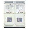
.Paralleling System Cabinet Equipment and Structure
1. Synchronous Controller
1. 1 Speed Adjuster:
This speed adjuster, which make the gensets speed and load within the allowable errors setting, is carried by diesel gensets; also it is controlled by the central controller when used in paralleling cabinet.
1. 2 Automatical Synchronizer:
Synchronizer is used to compare the phase and frequency of unparalleling genset with that of Busbar.when the phasic differences happen, synchronizer will send out electricity signal, which can accelerate or slow down the genset speed based that phasic angle of genset keeps ahead or get behind the phasic angle of Busbar and is directly proportional to the phasic differences.when the phase and frequency are matched with the special appointed locking time within the limited setting, synchronizer will turn off a group of the contact point operated under the normal condition and close the load air switches through relay control.
1.3 Central Controller
Controller is integrated of electronic speed adjustor and power balancer,prior to the paralleling, controller receive the signal from antomatic synchronizer to change the genset operating speed and make the frequency and phase of genset equal to that of Busbar, after paralleling, first comparing the actual efficient load power of genset with the average voltage value of the total load, second comparing the genset frequency of electric signal pressure with the setting frequency, then overlay the two value differences to output control signal of speed adjustment, and also make efficient load power distribute the charge as per pre-setting load distribution parameter.
1.4 Slow-speed Synchronous DisplayS
Once voltage is approaching frequency approximately, the display indicator will come and go between - and + slowly, when the wave shape of Busbar is same as that of genset, SCREEN will demonstrate that the synchronism is happening simultaneously at the location of same-phase.
2. Measurement instrument
2.1 Power Meterpower meter examines the genset charge.
2.2 Alternating Ampere meterAmpere meter examines the phasic current.
2.3 Alternating VoltmeterVoltmeter examines the line voltage and phasic voltage that are chosen by Voltage Choice Switches.
2.4 Frequency MeterFrequency meter examines the voltage frequency.
3. Synchronous Protector
3.1 Reverse-power protectorReverse power protection device examines the genset power load. If the reverse power can reach the presupposition level(the adjustment extent within 2%--20%) within the predetermined time(the adjustment extent within 2%--20%), the load switches break up. In order to prevent one genset from dragging from another one, these preadjustment are limited within 5 seconds under or below the 20% reverse power
3.2 Protecting Device of Emergency Stop
if there is something emergency with genset or paralleling system cabinet, press the button Emergency Stop on the paralleling cabinet to make the load switch to break up, then the gensets will be stopped.
4. Indication light of Controlling Cabinet
4. Gesent Malfunctionwhen the indication light is on, there will be possible malfunctions with low oil pressure or high water temperature.
4.2 Reverse power malfunctionwhen the indication light is on, there will be possible malfunction with backwash among gensets when paralleling.
4.3 Awaiting Indicator when the light is on, the gensets are in the condition of awaiting.
4.4 Operating Indicator the light will be on when the gensets work normally
4.5 Breaking-up Indicatorwhen the light is on, the load air switch is in the condition of beaking-up.
4.6 Connecting Indicator when the light is on, load air switch is in the condition of connecting.
4.7 Generator Indicatorwhen the light is on, gensets have putout the voltage to paralleling system cabinet