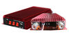

walkie talkie amplifier two way radio amplifier FM tranceiver amplifier CB radio power amplifier
Auto protect
HF/VHF/UHF
Net weight: 750gDimension: 109x225x35 mm
Packaging Spec: 230*120*40mm SSB output power: PEP Max 300 W(Input 10W)Frequency Range: 3-30MHZ (20-30 MHz is the best)
Blown fuse: 2x12 ATurn on/off switch Auto receive CB radio amplifier
Auto mode
Operate voltage: 12-14 Vcc Input current/POWER: 14-20 A Input power: 1-5 WSSB input power: 2-10 W FM Output power: Max 150 W(Input 10W) AM Output power: Max 150 W(Input 10W)SSBoutput power: Max 300 W(Input 10W) Max 250W (Input 5W )Working mode: FM- AM-CW-SSB Net weight: 750 g
Specifications
Introduction
There are some important updates to this project, as shown below. Recent testing has shown that with the new ON Semi transistors it is possible to obtain a lot more power than previously. The original design was very conservative, and was initially intended to use 2SA1492 and 2SC3856 transistors (rated at 130W) - with 200W (or 230W) devices, some of the original comments and warnings have been amended to suit.
WARNINGS:
This amplifier is not trivial, despite its small size and apparent simplicity. The total DC is over 110V (or as much as 140V DC!), and can kill you.The power dissipated is such that great care is needed with transistor mounting.The single board P68 is capable of full power duty into 4 Ohm loads, but only at the lower supply voltage.For operation at the higher supply voltage, you must use the dual board version.There is NO SHORT CIRCUIT PROTECTION. The amp is designed to be used within a subwoofer or other speaker enclosure, so this has not been included. A short on the output will destroy the amplifier.DO NOT ATTEMPT THIS AMPLIFIER AS YOUR FIRST PROJECT
Description
Please note that the specification for this amp has been upgraded, and it is now recommended for continuous high power into 4 Ohms, but You will need to go to extremes with the heatsink (fan cooling is highly recommended). It was originally intended for "light" intermittent duty, suitable for an equalised subwoofer system (for example using the ELF principle - see the Project Page for the info on this circuit). Where continuous high power is required, another 4 output transistors are recommended, wired in the same way as Q9, Q10, Q11 and Q12, and using 0.33 ohm emitter resistors.
Continuous power into 8 ohms is typically over 150W (250W for ±70V supplies), and it can be used without additional transistors at full power into an 8 ohm load all day, every day. The additional transistors are only needed if you want to do the same thing into 4 ohms at maximum supply voltage! Do not even think about using supplies over ±70V, and don't bother asking me if it is ok - it isn't!
The circuit is shown in Figure 1, and it is a reasonably conventional design. Connections are provided for the Internal SIM (published elsewhere on the Project Pages), and filtering is provided for RF protection (R1, C2). The input is via a 4.7uF bipolar cap, as this provides lots of capacitance in a small size. Because of the impedance, little or no degradation of sound will be apparent. A polyester cap may be used if you prefer - 1uF with the nominal 22k input impedance will give a -3dB frequency of 7.2Hz, which is quite low enough for any sub.
The input stage is a conventional long-tailed pair, and uses a current sink (Q1) in the emitter circuit. I elected to use a current sink here to ensure that the amp would stabilise quickly upon application (and removal) of power, to eliminate the dreaded turn on "thump". The amp is actually at reasonably stable operating conditions with as little as +/-5 volts! Note also that there are connections for the SIM (Sound Impairment Monitor), which will indicate clipping better than any conventional clipping indicator circuit. See the Project Pages for details on making a SIM circuit. If you feel that you don't need the SIM, omit R4 and R15.
The Class-A driver is again conventional, and uses a Miller stabilisation cap. This component should be either a 500V ceramic or a polystyrene device for best linearity. The collector load uses the bootstrap principle rather than an active current sink, as this is cheaper and very reliable (besides, I like the bootstrap principle :-)
Fuses are shown as 10A, and this is enough for normal operation from ±56V. If you use the dual board version and ±70V supplies, you'll need to increase the fuse rating to around 12A. Feel free to use 15A fuses ragardless of supply voltage, as they are only there to protect the power transformer from a short - they cannot protect the amplifier.
It is in the output stage that the power capability of this amp is revealed. The main output is similar to many of my other designs, but with a higher value than normal for the "emitter" resistors (R16, R17). The voltage across these resistors is then used to provide base current for the main output devices, which operate in full Class-B. In some respects, this is a "poor-man's" version of the famous Quad current dumping circuit, but without the refinements, and in principle is the same as was used in the equally famous Crown DC300A power amps.
Although I have shown MJL4281A and MJL4302A output transistors, because they are new most constructors will find that these are not as easy to get as they should be. The alternatives are MJL3281/ MJL1302 or MJL21193/ MJL21194.
Note: It is no longer possible to recommend any Toshiba transistors, since they are the most commonly counterfeited of all. The 2SA1302 and 2SC3281 are now obsolete - if you do find them, they are almost certainly fakes, since Toshiba has not made these devices since around 1999~2000.
Use a standard green LED. Do not use high brightness or other colours, as they may have a slighty different forward voltage, and this will change the current sink's operation - this may be a miniature type if desired. The resistors are all 1/4W (preferably metal film), except for R10, R11 and R22, which are 1W carbon film types. All low value resistors (3.3 ohm and 0.33 ohm) are 5W wirewound types.
Because this amp operates in "pure" Class-B (something of a contradiction of terms, I think), the high frequency distortion will be relatively high, and is probably unsuited to high power hi-fi. At the low frequency end of the spectrum, there is lots of negative feedback, and distortion is actually rather good, at about 0.04% up to 1kHz. My initial tests and reports from others indicate that there are no audible artefacts at high frequencies, but the recommendation remains.
Power Dissipation ConsiderationsI have made a lot of noise about not using this amp at ±70V into 4 ohms without the extra transistors. A quick calculation reveals that when operated like this, the worst case peak dissipation into a resistive load is 306W (4Ω/ ±70V supplies). The four final transistors do most of the work, with Q7 and Q8 having a relatively restful time (this was the design goal originally). Peak dissipation in the 8 output devices is around 70W each.
Since I like to be conservative, I will assume that Q7 and Q8 in the updated schematic shown contribute a little under 1A peak (which is about right). This means that their peak dissipation is around 18W, with the main O/P devices dissipating a peak of 70W each. The specified transistors are 230W, and the alternatives are 200W, so why are the extra transistors needed?
The problem is simple - the rated dissipation for a transistor is with a case temperature of 25°C. As the amp is used, each internal transistor die gets hot, as does the transistor case - the standard derating curves must be applied. Add to this the reactive component as the loudspeaker drives current back into the amp (doubling the peak dissipation), and it becomes all too easy to exceed the device limits. The only way that this amp can be used for continuous high power duty with ±70V supplies and a 4Ω loudspeaker load is to keep the working temperature down to the absolute minimum - that means four output devices per side, a big heatsink and a fan!
Figure 1A shows the doubled output stage, with Q9, Q10, Q11 and Q12 simply repeated - along with the emitter resistors. Each 1/2 stage has its own zobel network and bypass caps as shown, as this is the arrangement if the dual PCB version is built. When you have this many power transistors, the amp will happily drive a 4 ohm load all day from ±70V - with a big enough heatsink, and forced cooling. Over 500W is available, more than enough to cause meltdown in many speakers!
A Few Specs and MeasurementsThe following figures are all relative to an output power of 225W into 4 ohms, or 30V RMS at 1kHz, unless otherwise stated. Noise and distortion figures are unweighted, and are measured at full bandwidth. Measurements were taken using a 300VA transformer, with 6,800uF filter caps.
Mains voltage was about 4% low when I did the tests, so power output will normally be slightly higher than shown here if the mains are at the correct nominal voltage. Figures shown are measured with ±56V nominal, with the figure in (brackets) estimated for ±70V supplies.
| 8Ω | 4Ω | |
| Voltage Gain | 27dB | 27dB |
| Power (Continuous) | 153W (240W) | 240W (470W) |
| Peak Power - 10 ms | 185W (250W) | 344W (512W) |
| Peak Power - 5 ms | 185W (272W) | 370W (540W) |
| Input Voltage | 1.3V (2.0V) RMS | 1.3V (2.0V) RMS |
| Noise * | -63dBV (ref. 1V) | -63dBV (ref. 1V) |
| S/N Ratio * | 92dB | 92dB |
| Distortion | 0.4% | 0.4% |
| Distortion (@ 4W) | 0.04% (1 Khz) | 0.04% (1 Khz) |
| Distortion (@ 4W) | 0.07% (10 kHz) | 0.07% (10 kHz) |
| Slew Rate | > 3V/us | > 3V/us |
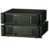
As can be seen, this is the single board version. The driver transistors are in a row, so that a single sheet aluminium heatsink can be used for all three. Holes are provided on the board so the driver heatsink can be mounted firmly, to prevent the transistor leads breaking due to vibration. This is especially important if the amp is used for a powered subwoofer, but will probably not be needed for a chassis mounted system. You may note that the 5W resistors are 2.2 ohm and 0.22 ohm on this board. These values can be used, but I recommend those shown in the schematic(s).
The driver heatsink shown is adequate for all power ratings with normal programme material. The power transistors are all mounted underneath the board, and the mounting screw holes can be seen on the top of the board.
Deceptively simple, isn't it?
+SHOUAO TS-300 amplifier for walkie-talkies or two-way radios